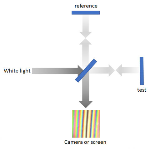
In the first 2 blogs in this series, we discussed what a wavefront is and how to specify it for your optical filter manufacturer. The next two posts describe how we measure such a thing as transmitted wavefront distortion (TWD) or reflected wavefront distortion (RWD) at Omega.
One of the most common methods used to measure wavefront error is interferometry. As the name suggests, this method uses interference between the part under test and a flat reference sample held at a very slight angle. When both pieces are perfectly flat, the light from the two surfaces interacts to form a series of constructively (bright) and destructively (dark) interfering lines (fringes). For best results and the clearest fringes, an expanded laser beam is used as the light source. The smaller the angle between the two parts or the longer the wavelength of light used, the fewer lines you will see across the part.
What happens when the piece being tested is not flat? The constructive and destructive interference fringes no longer look like a series of straight parallel lines. The lines warp from straight. They can be curved or wavy depending on the surface. If you were to measure a lens, you would see a series of concentric circles. This pattern of light and dark areas is called an interferogram. The surface shape can be calculated from the interferogram, but many customers are accustomed to looking at interferograms directly. Omega routinely uses interferometry (Zygo or Davidson interferometers) to measure uncoated glass and filter products with flatness less than ¼ wave per inch. For more highly curved or stressed filters, we typically use a Shack-Hartmann wavefront sensor, which will be discussed next month in the last blog of the Making Waves series.
Download our tech note to learn more about wavefront distortions and interferometry!
