Fluorescence is a very sensitive technique used commonly in medical diagnostics, biology, chemistry, materials science and mineralogy. It works by exciting a molecule with light of a particular wavelength (or color) and looking for emission (the release of light) at another color. Usually, the excitation wavelength is lower than the emission wavelength. Fluorescence is favored in diagnostics because of the extremely high signal to noise ratio. Scientists can detect the fluorescence from a single molecule with the right filters and optical geometry.
Already a fluorescence expert? Click here for our spectral viewer- curvomatic!
Three common geometries of fluorescence systems
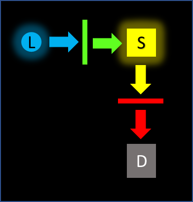
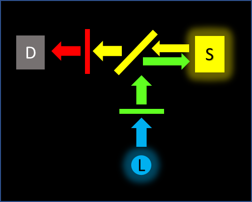
In the diagrams below, the blue "L" denotes the light source, the yellow "S" denotes the sample and the grey "D" denotes the detector. Filters are indicated with colored lines. The light paths and directions are indicated with arrows. Focusing optics have been omitted for clarity, but it should be noted that they are required to reduce the angles-of-incidence hitting the filters to maximize the spectral performance.
Linear fluorescence geometry

This is often seen in multiphoton microscopy and is less common in fluorometer (radiometric) applications. The excitation beam passes through the sample and into the detection path. Strong blocking of the excitation wavelengths (greater than OD6, as high as OD10) is required because both the unabsorbed excitation light and the emission (signal) are directed towards the detector. Some surface defects, but no pinholes can be tolerated to achieve the high ODs required.
Perpendicular fluorescence geometry

This is common in fluorometer (radiometric) applications, clinical diagnostics and flow cytometry. The excitation light path is perpendicular to the detection path. Excitation light only enters the detection path through scatter in the sample. An emission filter is always used to block scattered excitation light.
Deep blocking of the excitation light is generally not required unless the sample is turbid or highly scattering. As this technique measures total signal, some surface defects and pinholes in the emission filter can be tolerated as long as the blocking specifications are maintained.
Reflected fluorescence geometry

This is common in fluorescence microscopy. The excitation light and emitted light partially share a path travelling in different directions. Filtered excitation light is steered toward the sample using a wavelength-selective mirror called a dichroic. Often placed at 45 degrees, the dichroic reflects the excitation wavelengths and transmits the emission wavelengths toward the detector. An emission filter is also placed in front of the detector to increase blocking and refine the wavelengths. In fluorescence microscopes, the 3 filters are often installed in a "cube" and sold as a set.
View our fluorescence sets with your fluorophores in curvomatic.
As in the case for the perpendicular geometry, extremely high blocking is not generally required. Excitation light is blocked by the dichroic and the emission filter in combination. The emission transmission can be calculated by multiplying the dichroic and emission filter spectral responses.
Excitation filters and fluorescence light sources
In order to excite the molecule of interest, the light hitting that molecule has to be of a particular color. Many light sources are already monochromatic or emit a narrow range of colors. These include lasers, LEDs (light emitting diodes) and SLDs (super luminescent diodes). Researchers should look at the spectral distribution of the light sources to determine if there is any light being emitted at the detection wavelength. These light sources often have low-intensity emissions near the peak emission that should be filtered out. Cleanup filters (a bandpass or shortpass filter) can eliminate noise signals that will increase the fluorescence background. The blocking range of these filters can be limited since most of the confounding signal is close to the desired wavelengths.
For broadband sources, such as arc lamps, excitation filters are required to shape the spectral profile. They are also required to block light over an extended wavelength range that includes the detector’s response curve.

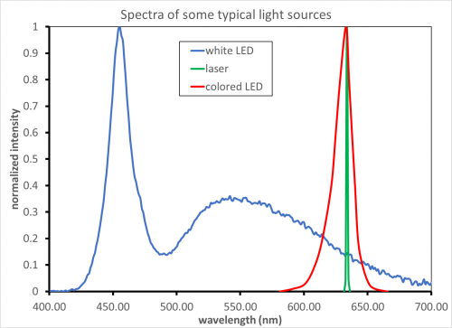
For example, consider the 3 sources above used for excitation of a fluorophore with a peak excitation at 630 nm and emission between 650 and 700 nm.
The laser (green trace) emits over only a very narrow range- you can use a laser cleanup filter (a few nm wide) with low levels of blocking to eliminate any ASE (amplified spontaneous emission) signal. Extended blocking of the visible is not needed.
Similarly, the colored LED (red trace) only emits over a limited range. The most important wavelengths to block for the LED are those that directly overlap with the emission channel (in this case 650-700nm). A shortpass filter at 635 nm, or a bandpass would work to block any LED light from scattering into the detection channel. Deep blocking over the emission range will be required while “short side” blocking is less important in this case.
In contrast, the white-light LED (blue trace) emits light over a large wavelength range including all of the visible and the emission wavelengths. A bandpass filter with full blocking over the entire range of the detector is required (typically 300-1100 nm for Silicon detectors, but this varies significantly). Extra blocking will be required in the 425-475 nm region to reduce the contribution of the lamp output in this region, as well as over the emission wavelengths.
