Submitted by ashrollend on Thu, 12/17/2020 - 11:51
A Quick Look Into AOI and 1/2 Cone Angles
filters

Understanding AOI is an integral part of the filter-purchasing process. For those looking to optimize AOI and cone angle requirements, we suggest you read on - from steering optics to interference filters, this blog addresses the many different influences on AOI that might not be recognizable to the naked eye. Our products ensure you get the best, most refined spectral response possible - but why not learn a bit more about the science behind this phenomenon?

Angle of incidence and cone angle

In optics, all angles are measured with respect to the normal (perpendicular to the surface). This includes the angle of incidence (AOI), angle of reflection and angle of refraction. The AOI is the average angle at which the light hits the surface. If the light beam comes in perpendicular to the surface, the AOI is zero.

Some light beams are collimated, meaning all the light is moving in the same direction These beams are not being focused or defocused. In this case, the cone angle is also zero. The cone angle describes the deviation of the AOI in a converging or diverging beam. It is often expressed as a half cone angle in a tolerance. For instance, a beam with an AOI of zero might have a distribution of angles (cone angle) of + 20 degrees. The cone of light hitting the surface will contain a total of 40 degrees centered around zero.

For steering optics (mirrors and dichroics), this can become more complicated. You may have an example where the AOI is 45 degrees with a ½ cone angle of 10 degrees (or + 10 degrees). The light hitting the surface will contain light at all angles between 35 degrees and 55 degrees. See our AOI tech notefor more information about cone angles and how they relate to f/# and numerical aperture.

Why do AOI and ½ cone angle matter for interference filters?

Interference filters work by layering thin-films of materials with different refractive indices (high and low) in an alternating pattern on a substrate. By keeping the layers and materials constant and only changing the AOI, it can be shown that the wavelength of maximum interference is proportional to the cosine of the AOI. In a bandpass filter, for example, the peak transmission wavelength will decrease as the AOI increases. Remember, cosine of zero degrees (AOI=0) is 1 and cosine of 90 degrees (parallel to the surface, AOI=90) is zero. The greater the AOI, the lower the cosine and the lower the observed wavelength.

Increasing the cone angle causes both a lowering of the center wavelength and a broadening of the spectral response. The beam described by the cone angle contains light at all the intervening wavelengths. So, the response of a 20 degree half cone angle is the response of all angles between 20 and zero added together. Because filter design includes the AOI in its optimization, it is difficult to design a filter that will work well at large cone angles.

Omega Optical has been developing new coating materials to mitigate the effect of angle on the spectral response. We can also help you to optimize the AOI and cone angle requirements for your system. Contact a member of our team today.

By
Sarah Locknar
Category
Application Spotlights
Tags
Interference Filters

Coating Methods and Materials

https://www.omegafilters.com/capabilities/coating-methods-and-materials
The Optical Coating Process

There are several deposition technologies employed to manufacture filters. At Omega, these include evaporative methods and sputtering. All methods utilize materials of different refractive indices to control portions of the electromagnetic spectrum.

FRET

https://www.omegafilters.com/applications/fret
FRET Overview

FRET, or Forster Resonance Energy Transfer, is a phenomenon where closely matched pairs of fluorophores are used to determine spatial proximity in molecular and protein-protein interactions.

Filters on Fiber Tips

https://www.omegafilters.com/product-types/coated-fiber-tips

What started as a research project has turned into one of Omega's most unique capabilities- coating the tips of fiber optics with spectrally-complex coatings including broadband antireflection coatings, reflectors and our full-range of filters.

Submitted by slocknar on Wed, 10/20/2021 - 14:59
An introduction to n and k
bubbles

Refractive index is a dimensionless quantity that describes the speed of light in a medium with respect to the speed of light in vacuum. Most materials have a refractive index > 1 which means that light travels slower in a medium than it does in vacuum. The higher the refractive index, the slower the light moves in that medium. When a researcher looks up “the refractive index” of a material in a book, it is often reported as single number, but it’s not that simple.


In reality, refractive index is a complex number comprised of a real part (n) and an imaginary part (k). The real part, as described above, describes the speed of light in the material. The imaginary part of the refractive index is the extinction coefficient in the material - a measure of how much light is being absorbed at a given wavelength. Both n and k are wavelength dependent, so they vary over the spectrum.


The refractive index of a thin film can also vary significantly from that of the bulk material reported in books. The refractive index of a thin-film depends on a myriad of process conditions including deposition rates, gas flow rates, oxidation plasma parameters, base vacuum pressure, etc. Small changes in these parameters can affect the film structure and density which in turn affect the refractive index and the final product.


Interference filters are typically made with materials that do not exhibit absorption (k) in the wavelengths of interest, so that part of the refractive index can be neglected. Interference filters work because of constructive and destructive interference between alternating layers of high refractive index (n) and low refractive index materials. The most basic interference filter is a quarter wave stack. A “quarter wave” occurs when the product of the refractive index and the physical thickness of a layer is equal to ¼ of the wavelength being observed. Thin-film designers refer to this product as the optical thickness. Our thin-film design software calculates the required physical thicknesses of each layer to achieve desired spectral performance, but we often monitor film growth using optical thickness. Needless to say, this would be impossible without having tight control over the refractive index in our layers.


Next time in the blog, find out more about how we measure refractive index and keep our processes running optimally for a consistent product.     

By
Sarah Locknar
Category
Application Spotlights
Tags
Manufacturing

Filters for Defense Applications

https://www.omegafilters.com/MilAeroAstro/Filters-in-Defense

Omega has a long history of supplying filters for a range of combat applications - from training simulators to surveillance, autonomous vehicles to wearable night-vision goggles - each has unique requirements and specifications. Omega is fully equipped with testing equipment including thermal cycling, heat & humidity cycling, salt fog and spray, and abrasion testing.

Color Imaging

https://www.omegafilters.com/applications/color-imaging
Image Enhancement, Color Separation, Color Correction

Color imaging systems benefit from the use of precision optical filters which control the spectral properties of light and color separation to exacting tolerances.

UV Filters

https://www.omegafilters.com/product-types/uv-filters

Omega has been manufacturing UV filters for over 50 years. UV light (in the 200 nm - 400 nm range) has many commercial and consumer-level applications. UV light can be used in photolithography or dentistry to photoset polymers, and in biomedical applications to excite molecules during surgery. It can be used to measure DNA and to sterilize our water and the air we breathe. While useful for many things, it can also be harmful.

Submitted by ashrollend on Mon, 10/12/2020 - 10:55
An In-Depth Look into Fluorescence Microscopy Filters
Filter Set / Cube

Using a microscope for the first time can be a profound experience. Suddenly, you can observe the world on a scale that is otherwise invisible to the naked eye. Imagine being one of the first researchers to combine multiple optical lenses and resolving organisms or structures that were previously just theoretical: Bacteria, cellular structures, and so on. The effect would have been sensational – and with good reason. The onset of microscopy pioneered new schools of thought while compound microscopes gradually became a staple instrument in virtually every research facility on the planet. It is odd to think that this ground-breaking success all hinged on a few lenses - and has since advanced to one of the most innovative, technical fields in the world of science. Thanks to microscopy and the development of microscopy filters, we now experience and understand life in a way we never thought possible.

Microscopy Filters 101

Lenses and filters are a staple of any instrument concerned with the physico-optical properties of sample materials. They are critical for observing the way that light of specific wavelengths reflects, scatters, diffracts off a surface, or is absorbed and emitted by it. This is how you can visualize the minute spatial and structural properties of samples under test. When you are observing weak emission signals like fluorescence or phosphorescence, you must use highly specialized microscopy filters.  

The Main Components of Microscopy Filter Sets

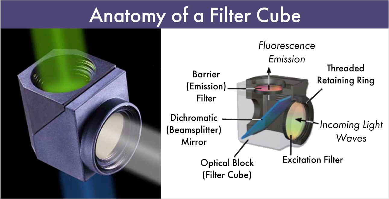
  1. An excitation filter, which is integrated into a cube, slider or wheel positioned in the light excitation path – between the light source and the objective lens;
  2. A dichroic mirror, which performs the dual function of reflecting excitation light to the sample while transmitting emission signals through to the eyepiece or detector;
  3. An emission filter, which is positioned between the objective lens and the eyepiece to screen out signals that are irrelevant to sample fluorescence (i.e. stray excitation light).  

The Principles of Microscopy Filters

Though there is no universal workflow to explain how all fluorescence microscopy filters work, there is a set of basic principles that are worth bearing in mind when it comes to selecting your filter set.

Fluorescence microscopy concerns relatively weak emission signals only emitted by certain materials. These photo-luminescent compounds absorb light of specific wavelengths and emit photons when excited. Fluorophores typically stop fluorescing as soon as the excitation source is removed. The purpose of the fluorescence set is to direct the excitation wavelengths toward the sample and the emission wavelengths toward the detector.  These are often housed in "cubes" with the excitation filter pointing towards the light source and the emission filter pointing towards the detector with the dichroic in between. The dichroic filter enables the entire setup. It serves two functions- as a steering mirror to reflect the excitation light into the sample and as a wavelength selector- passing emission wavelengths through towards the detector. 

Anatomy of a Filter Cube-Emission, Dichroic, Excitation

Once the filtered excitation light has passed through the excitation filter, it reflects off the dichroic mirror at a 45° angle and excites the fluorophores in the sample. The dichroic mirror is vital as it can reflect over 90% of the excitation light while transmitting over 90% of the emission light.

The longer wave fluorescence signals pass through the emission filter which performs a similar function to the exciter in that it passes a range of wavelengths while thoroughly blocking the excitation wavelengths. What is left produces the high contrast image of fluorescently-stained molecules on a black background. 

Microscopy Filters from Omega Optical

As we have explained throughout this article, the performance of each of these components is based purely on their ability to selectively attenuate, transmit, or reflect light of specific wavelengths or within a given spectral region. You can typically distinguish between microscopy filters as either short- or long-pass filters, which governs which end of the electromagnetic spectrum their waveband is based in. The filter set you employ depends on your application and your labeling parameters. If you would like to experiment with fluorescence sets and fluorophores, try our Curvomatic. 

Compare Fluorescence Sets and Fluorophores

Or, if you would like to speak with a member of the Omega Optical team about specific microscopy filters for your application, simply contact a member of the team today. 


By
Ben Stibbs
Category
Application Spotlights
Tags
Fluorescence
Filter Set

Terms and Conditions

https://www.omegafilters.com/resources/terms-and-conditions
Updated May 23, 2024


OMEGA OPTICAL HOLDINGS, LLC

TERMS AND CONDITIONS OF SALE